What Are Angular Contact Bearings?
Angular contact bearings are ball bearings whose inner and outer raceways are offset relative to each other, so the balls touch each raceway along a line set at an angle to the bearing's radial plane. That angle — called the contact angle — is what lets a single bearing carry radial load and axial (thrust) load in one direction at the same time, something a standard deep groove ball bearing cannot do efficiently. Angular Contact Ball Bearings (ACBBs) are built with one raised shoulder on the outer ring and one lowered shoulder, creating the asymmetry needed to transmit thrust load through the ball-to-race contact point.
Standard contact angles used across the bearing industry are 15°, 25°, and 40°, with 30° also appearing in some manufacturer ranges. The rule of thumb is simple: a larger contact angle carries more axial load but tolerates less speed; a smaller contact angle spins faster but carries less thrust. Because a single-row angular contact bearing can only resist thrust from one direction, most applications mount two bearings as a matched pair to handle load coming from both sides of the shaft.
How Angular Contact Ball Bearings Work
Inside a deep groove ball bearing, the raceway grooves are symmetrical and the ball sits centered between them — the contact angle is essentially zero, so the bearing mainly resists radial load. In an angular contact bearing, the outer ring groove is shifted axially relative to the inner ring groove. When a ball sits between two offset grooves, the line connecting its two contact points is no longer perpendicular to the shaft — it's tilted. That tilt is the contact angle (α), and it's what converts part of any radial push into a load path capable of resisting axial thrust.
Free, Static, and Dynamic Contact Angles
Bearing catalogs quote a "free" or nominal contact angle (15°, 25°, 40°) measured with the bearing unloaded and unmounted. Once the bearing is press-fit onto a shaft, subjected to thermal expansion, and put under operating load and centrifugal force from rotation, the actual — or effective — contact angle shifts from that nominal figure. If the contact angle increases too much, the ball can ride up past the raceway shoulder and cause premature failure; if it drops too low, balls can bind in the raceway or lose preload, leading to erratic ball motion and early wear. This is why bearing engineers calculate both static and dynamic contact angle shifts before finalizing a fit and preload specification, rather than relying on the catalog angle alone.
Contact Angle Options: 15°, 25°, and 40° Compared
Choosing the right contact angle is the single most consequential decision in specifying an angular contact bearing, because it fixes the trade-off between speed and thrust capacity for the life of the application. Fifteen-degree bearings maximize speed capability with less axial load capacity, and are the best choice for high-speed spindles above roughly 15,000 RPM where axial load stays moderate. Twenty-five-degree bearings are the general-purpose, most widely stocked choice, balancing speed and axial capacity across the majority of precision gearboxes, robotics joints, and medium-speed spindles. Forty-degree bearings maximize axial load capacity but come with a significant speed penalty.
Comparison of standard contact angles used in angular contact ball bearings
| Contact Angle |
Speed Capability |
Axial Load Capacity |
Typical Use |
| 15° |
Highest |
Lowest |
High-speed spindles, grinding machines |
| 25° |
Moderate-high |
Moderate-high |
General-purpose gearboxes, pumps, motors |
| 40° |
Lowest |
Highest |
Ball screws, centrifugal pumps, thrust-heavy shafts |
A practical way to remember it: when radial load dominates the load case, a 25° bearing is the default; when axial (thrust) load dominates, step up to 40°; when the shaft needs to spin fast and axial load is light, drop to 15°. Manufacturers also encode the angle in the part number — for example, NSK uses the suffix "A5" to denote 25°, and many brands append "B" to a base part number to indicate 40° rather than the standard 30°, so always confirm the angle code against the specific manufacturer's catalog rather than assuming a universal suffix system.
Angular Contact Bearings vs. Deep Groove Ball Bearings
Angular contact and deep groove bearings often share the same bore, outside diameter, and width, which makes them look interchangeable on a drawing — but swapping one for the other under real load conditions can collapse L10 bearing life by 60–80%, or in worse cases cause seizure within hours of startup. The difference comes down entirely to that contact angle and the shoulder geometry it requires.
A 6206 deep groove ball bearing (30 mm bore) carries a dynamic radial load rating of roughly 19.5 kN, while a comparable 7206 angular contact bearing at 25° carries around 17.8 kN radially — about 9% less. Where the angular contact bearing pulls decisively ahead is on the thrust side: that same 7206 at 25° can handle continuous axial load up to roughly 8.5 kN, whereas an equivalent deep groove bearing is typically limited to only 30–40% of its dynamic radial rating in the axial direction, and only at low to moderate speeds. For any application with meaningful thrust — helical gear meshes, ball screws, angled cutting forces — a deep groove bearing simply runs out of axial capacity long before an angular contact bearing would.
Visual Identification
A deep groove bearing has two equal shoulders on either side of the ball groove, while an angular contact bearing has one tall shoulder and one low shoulder — the tall side is the load-bearing face and must face the source of thrust load during installation. Part numbering is another giveaway: angular contact ball bearings typically carry 7xxx series designations, while deep groove ball bearings use 6xxx series numbers.
Mounting Arrangements: DB, DF, and DT Explained
Because one angular contact bearing only resists thrust from one direction, most real installations use two (or more) bearings mounted as a matched, pre-adjusted pair. Bearings can be arranged with their outer ring front faces together (face-to-face, DF), with their back faces together (back-to-back, DB), or with their faces aligned in the same direction (tandem, DT). Choosing the wrong arrangement for the load case is one of the most common — and costly — specification errors.
Back-to-Back (DB)
In a back-to-back arrangement, the contact angle lines of the two bearings diverge inward, forming an "O" shape, which is why DB is also called the O-arrangement. DB pairing gives the strongest resistance to tilting moments, so it's the right choice whenever radial load combined with a tilting moment dominates the load case. This wide effective load-center spacing is why DB pairs are the standard choice for spindle noses and wheel hubs that must resist overturning forces.
Face-to-Face (DF)
In a face-to-face arrangement, the gap sits between the outer races rather than the inner races, and closing that gap on installation produces the working preload. DF pairing is the right call when axial load can come from both directions and the assembly needs to thermally compensate for shaft expansion, since the narrower load-center spacing tolerates shaft growth more gracefully than DB. The trade-off is lower resistance to moment loads, so DF pairs need adequate axial spacing if misalignment resistance matters.
Tandem (DT)
In a tandem arrangement, the contact angle lines of both bearings run parallel, producing a very heavy-duty thrust configuration that carries no radial load and accepts thrust in only one direction. DT pairing is the choice when unidirectional axial load is oversized for a single bearing, since the arrangement superimposes the axial capacity of both bearings. If thrust must be resisted from both directions in a tandem system, a third bearing has to be added against the tandem pair — DT alone provides no inherent axial stability without that extra preload.
Quick-reference guide to selecting DB, DF, or DT mounting arrangements
| Arrangement |
Axial Load Direction |
Moment Rigidity |
Best For |
| DB (Back-to-Back) |
Both directions |
High |
Spindles, wheel hubs, tilting moments |
| DF (Face-to-Face) |
Both directions |
Lower |
Thermal expansion tolerance, self-aligning setups |
| DT (Tandem) |
One direction only |
None (needs added preload) |
Heavy unidirectional thrust (ball screws, pumps) |
Common Types of Angular Contact Ball Bearings
Single-Row Angular Contact Bearings
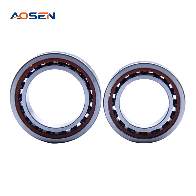
The baseline design: one row of balls, one raised shoulder, capable of carrying radial load plus axial load in a single direction. Used alone only where thrust is genuinely one-directional; otherwise mounted in a DB, DF, or DT pair.
Double-Row Angular Contact Bearings
Designed for high rigidity and combined radial and axial loads in both directions, double-row angular contact bearings are commonly used in motors, pumps, and compressors. They function like a permanent back-to-back pair built into a single bearing, sustaining axial loads in both directions while also handling moment loads, and are frequently used as the fixed-end bearing in a shaft system.
Four-Point Contact Bearings
Four-point contact bearings offer a compact, high-rigidity design that supports axial loads in both directions with limited radial load capacity, and are commonly found in motors, gearboxes, and pumps. Under radial load, the balls establish four points of contact with the inner and outer rings — under pure axial load, contact reduces to two points, similar to a standard angular contact bearing. This design lets a single bearing replace a matched pair where axial space is at a premium.
Duplex (Matched Pair) Angular Contact Bearings
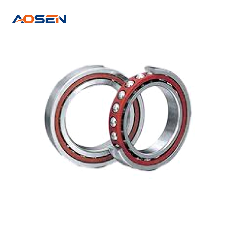
Duplex bearings are two or more single-row angular contact bearings manufactured and matched as a set to a specified clearance and preload, then mounted together in a DB, DF, or DT configuration. Because matched pairs must be produced in the same manufacturing batch to guarantee performance consistency, they should never be mixed with bearings from a different set — even if the part numbers appear identical.
Miniature Angular Contact Bearings
Miniature angular contact bearings are compact, high-precision versions of the standard single-row design, typically with bore sizes under 10 mm, built for space-constrained, precision-critical applications such as dental handpieces, optical instruments, and small servo actuators.
Preload: Why Angular Contact Bearings Need It
Angular contact bearings are typically assembled with a preload applied between the inner race, the balls, and the outer race, which minimizes or removes the internal clearance between the balls and both raceways. Without preload, an angular contact bearing under light or reversing load can develop ball skid, vibration, and premature wear as the balls momentarily lose consistent contact with the raceway.
Preload is closely tied to both contact angle and pairing arrangement, and getting it right is especially critical in high-speed, high-precision applications like spindles and servo motors, where correct preload improves rigidity and reduces vibration. The specific method — machined-in preload from the factory, spring preload, or preload set with tapered washers during installation — is usually determined at the installation stage rather than fixed at the design stage. Over-tightening preload is a common field mistake: excess clamping force drives up friction and heat, which can shorten bearing life just as much as running with too little preload.
Typical Applications of Angular Contact Ball Bearings
Angular contact bearings show up wherever a shaft experiences meaningful thrust load alongside radial load — which covers a wide swath of rotating machinery. A few of the most common applications illustrate why contact angle and mounting arrangement matter so much in practice:
- Machine tool spindles — from the ultra-precise spindles of CNC machine tools running at up to 30,000 RPM, where 15° bearings deliver the speed capability the process demands.
- Automotive wheel hubs — double-row angular contact bearings are the standard choice for modern car wheel hubs, easily handling the massive axial forces generated during high-speed cornering.
- Centrifugal pumps — the impeller pushes fluid forward, creating an equal and opposite thrust force back along the shaft, and 40° angular contact bearings absorb that thrust effortlessly.
- Ball screws and linear axes — precision automation requires zero backlash, and back-to-back-arranged angular contact bearings provide the rigid axial positioning needed for accurate robotic movement.
- Bicycle headsets — most bicycles use angular contact bearings in the headset because the forces acting there run in both the radial and axial directions.
- Gearboxes and turbochargers — matched angular contact pairs are widely used wherever bi-directional axial loads occur, including gearboxes, turbochargers, and robot joints.
How to Select the Right Angular Contact Bearing
Specifying an angular contact bearing correctly comes down to working through load direction, speed, and precision requirements in order — skipping any one of these steps is where most application-side failures originate.
- Identify whether axial load is unidirectional or bidirectional. Unidirectional loads can sometimes use a single bearing; bidirectional loads always require a matched pair or double-row design.
- Compare radial versus axial load magnitude. When radial load exceeds axial load, a 25° contact angle is the general-purpose choice; when axial load exceeds radial load, step up to 40° for its thrust-enhancement benefit; and for high-speed, light-load scenarios, 15° is preferred.
- Match the mounting arrangement to the dominant load type: DB back-to-back for radial load plus tilting moment (strongest anti-tilt resistance), DF face-to-face when bidirectional axial load must also accommodate thermal shaft expansion, and DT tandem when an oversized unidirectional axial load needs the combined capacity of multiple bearings.
- Check the limiting speed (theoretical maximum under ideal conditions), reference speed (recommended upper limit for stable long-term operation), and actual operating speed of the application against the bearing's rated values before finalizing the contact angle.
- For high-precision or high-speed spindle work, specify a precision class of P5 or above, since these classes are commonly used in machine tool main spindles where preload is adjusted based on operating conditions with a special fit.
- Confirm the manufacturer's angle-code convention (for example, an "A5" or "B" suffix) against the specific catalog rather than assuming it matches another brand's numbering.
Getting these six steps right up front — rather than defaulting to a familiar part number — is what separates a bearing that reaches its rated L10 life from one that fails early under a load case it was never actually suited to carry.

 Español

 +86-15990593443
 No. 558 Huancheng West Road, Zhouxiang Town, Cixi City, Ningbo Province, Zhejiang Province