Deep groove ball bearings are the most widely used bearing type in the world, accounting for roughly 80% of all rolling element bearing applications. Their defining feature — a deep, continuous raceway groove on both inner and outer rings — allows them to carry radial loads, moderate axial loads in both directions, and combined loads simultaneously, all with low friction and minimal maintenance.
They operate across an enormous speed and load range: standard designs handle speeds from near-zero to over 50,000 rpm in small precision variants, and dynamic load ratings from a few hundred Newtons in miniature bearings to over 250 kN in large industrial sizes. This versatility — combined with low cost, global availability, and decades of standardized design — makes deep groove ball bearings the default choice for electric motors, gearboxes, pumps, conveyors, automotive accessories, and consumer appliances worldwide.
How Deep Groove Ball Bearings Work
A deep groove ball bearing consists of four core components: an inner ring, an outer ring, a set of steel balls, and a cage (retainer) that maintains uniform ball spacing. The "deep groove" refers to the raceway profile — the groove depth is approximately 25–30% of the ball diameter, compared to just 10–15% in a shallow groove design. This deeper engagement is what enables the bearing to resist axial thrust loads without requiring a separate thrust bearing.
Load Transmission Mechanism
Under radial load, the applied force is distributed across the balls in the loaded zone — typically 3 to 5 balls carry the majority of the load at any given moment. The contact between each ball and the raceway is an elastic ellipse (Hertzian contact), not a point, which is why the bearing can handle significant loads without surface damage under normal operating conditions.
Under axial (thrust) load, the contact angle shifts from near-zero degrees to a maximum of approximately 45° as axial force increases. This is the physical limit of deep groove ball bearing axial capacity — beyond it, the balls ride up onto the groove shoulder and the bearing fails rapidly. As a guideline, the maximum sustained axial load should not exceed 50% of the static radial load rating (C0) for standard designs.
Friction and Running Characteristics
The rolling contact between balls and raceways generates far less heat than sliding contact in plain bearings. The coefficient of friction for a deep groove ball bearing is typically 0.001–0.0015 under ideal lubrication conditions — approximately 10–20 times lower than a well-lubricated plain sleeve bearing. This low friction translates directly to energy efficiency and reduced operating temperatures.
Deep Groove Ball Bearing Variants and Configurations
The basic open bearing design has been extended into numerous variants to address specific application requirements. Understanding the differences prevents specification errors that lead to premature failure or unnecessary cost.
Open (Unsealed) Bearings
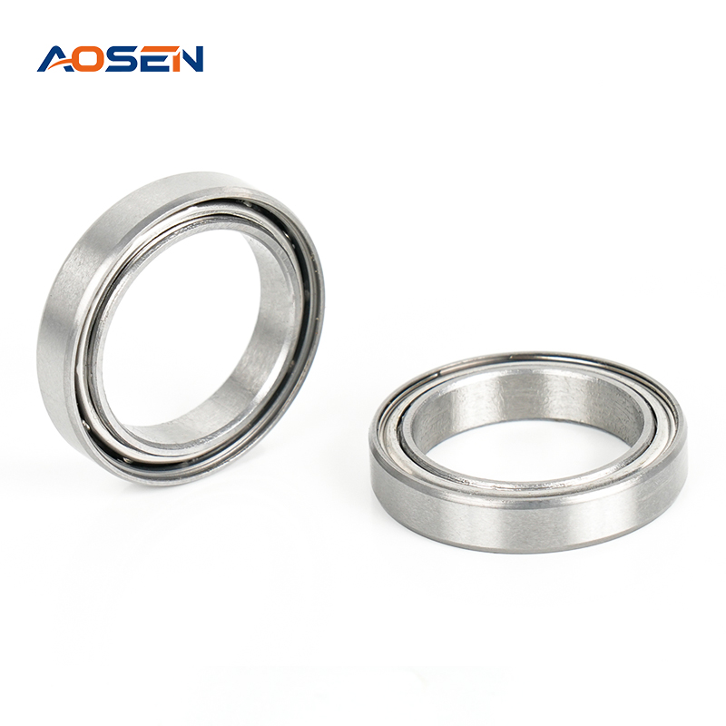
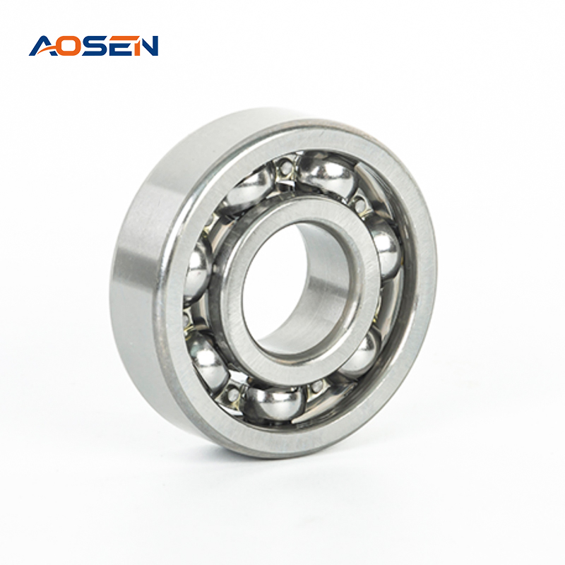
The standard open bearing has no seals or shields. It allows re-lubrication, runs at lower temperatures (no seal friction), and achieves the highest speed ratings of any variant. Used where the application provides its own sealed housing and centralized lubrication — such as gearboxes and industrial machinery with oil bath lubrication.
Shielded Bearings (ZZ / 2Z)
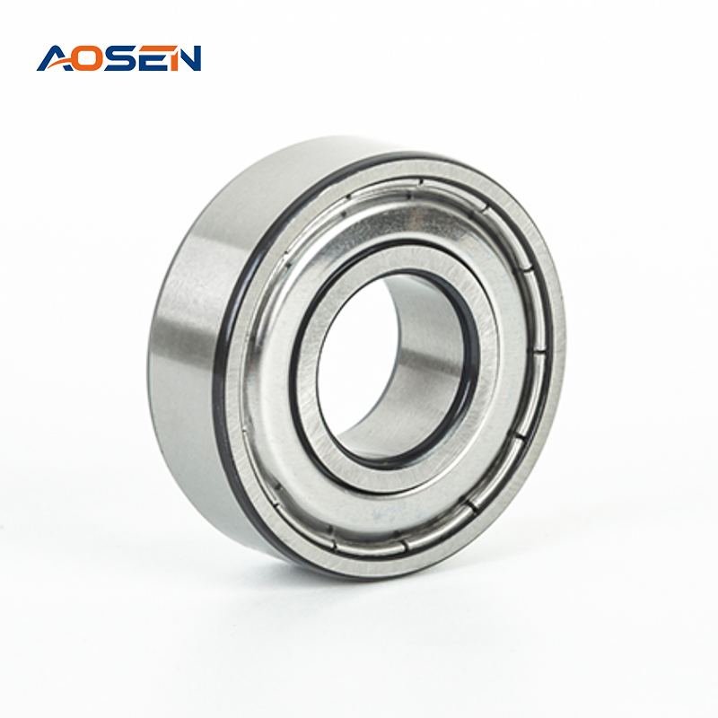
Metal shields on one or both sides protect against coarse contamination without contacting the inner ring. The small labyrinth gap means minimal additional friction and a speed rating penalty of only about 5–10% versus open bearings. Shields do not prevent fine dust or liquids from entering; they are suitable for moderately clean environments with re-lubrication access.
Sealed Bearings (RS / 2RS / RZ / 2RZ)
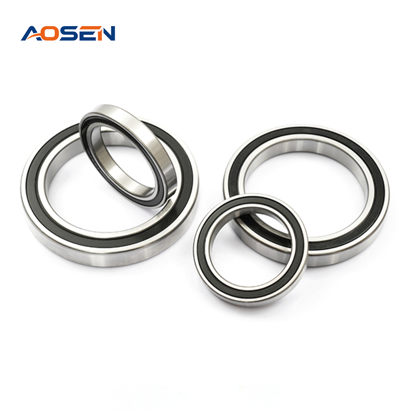
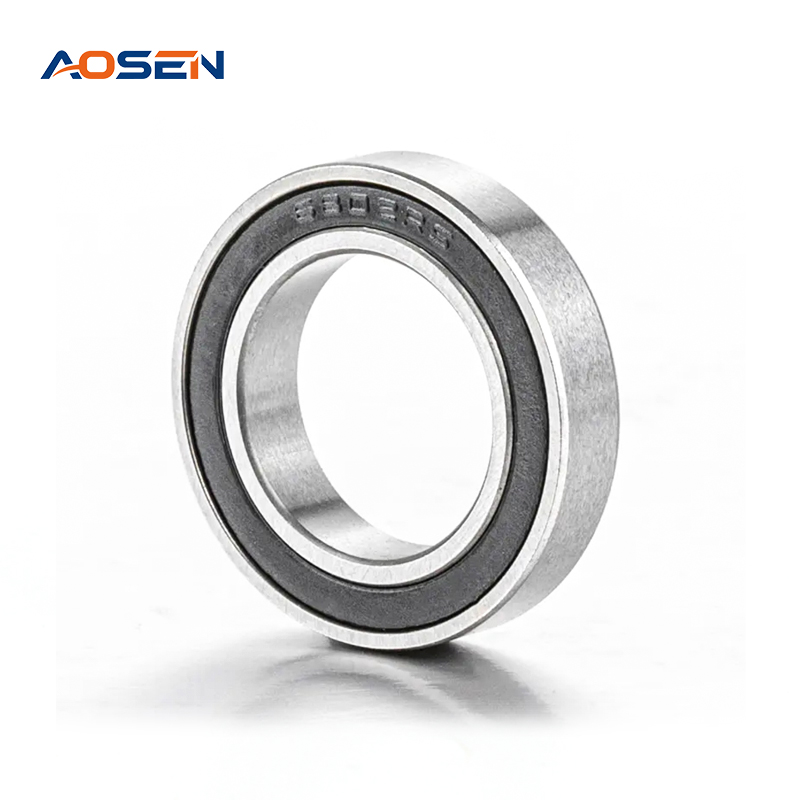
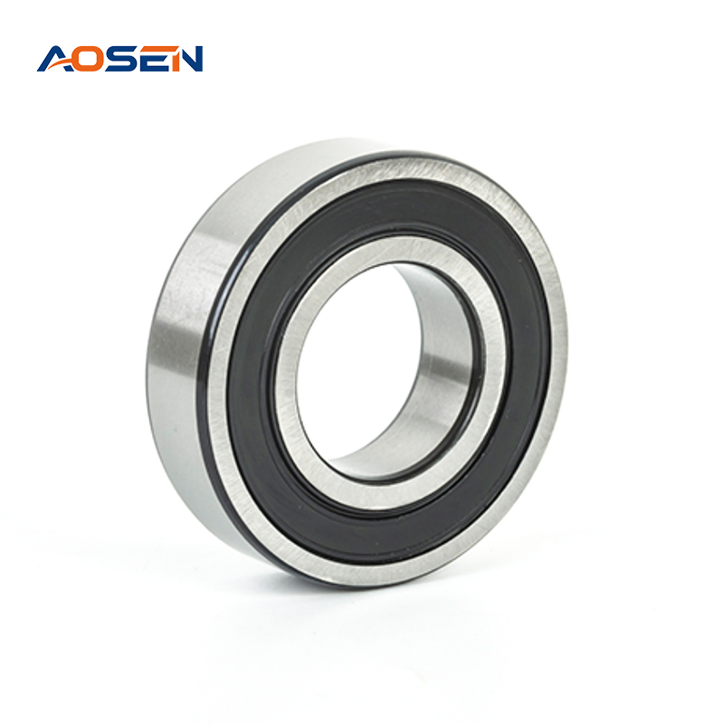
Elastomeric (rubber) seals contact or nearly contact the inner ring, providing effective exclusion of fine dust and moisture. The "RS" or "2RS" suffix denotes contact seals on one or both sides; "RZ" or "LLB" denotes low-friction non-contact (labyrinth) seals. Contact seals reduce maximum speed by approximately 20–30% but are pre-greased for life — no re-lubrication is needed or possible in most designs. The most common specification for consumer appliances, electric motors, and automotive auxiliary drives.
Snap Ring Groove Bearings (NR)
A circumferential groove on the outer ring accepts a snap ring for axial location in a housing without a machined shoulder. Simplifies housing design and reduces machining cost in applications like electric motor end shields.
Stainless Steel Bearings
Made from martensitic stainless steel (typically AISI 440C), these bearings offer corrosion resistance for food processing, marine, medical, and chemical environments. Load capacity is approximately 20–25% lower than equivalent chrome steel bearings due to the lower hardness achievable with stainless grades.
Hybrid Bearings (Ceramic Balls)
Silicon nitride (Si₃N₄) balls in steel rings reduce density by about 60% compared to steel balls, cutting centrifugal forces at high speed. Hybrid bearings achieve 20–30% higher speed limits, generate less heat, and are electrically insulating — preventing current-induced raceway fluting damage in variable-frequency drive motors.
ISO Designation System and How to Read a Bearing Number
Deep groove ball bearings are standardized under ISO 15 and ISO 355. Once you understand the numbering system, you can decode any bearing's basic dimensions and configuration from its part number alone.
A standard bearing number follows the format: [Type prefix][Series][Bore code][Suffix]. For example, the common bearing 6205-2RS1 breaks down as:
- 6 — Deep groove ball bearing (type designation)
- 2 — Light series (02 series): defines the relationship between bore and outer diameter
- 05 — Bore code: multiply by 5 to get bore diameter in mm → 05 × 5 = 25 mm bore
- -2RS1 — Two rubber contact seals (SKF designation; equivalent suffixes vary by manufacturer)
ISO dimension series for deep groove ball bearings: relationship between bore code and key dimensions across the main series.
| Series |
Description |
Example Bearing |
Bore (d) |
OD (D) |
Width (B) |
Typical Use |
| 60xx (Extra light) |
Smallest OD for bore |
6005 |
25 mm |
47 mm |
12 mm |
Light-load, space-constrained |
| 62xx (Light) |
Most common series |
6205 |
25 mm |
52 mm |
15 mm |
Motors, pumps, gearboxes |
| 63xx (Medium) |
Larger OD, higher load |
6305 |
25 mm |
62 mm |
17 mm |
Heavy industrial, conveyors |
| 64xx (Heavy) |
Largest OD for bore |
6405 |
25 mm |
80 mm |
21 mm |
Very heavy loads, low-speed |
For bore sizes below 20 mm, the bore code is not multiplied by 5 — instead, the actual bore in mm is written directly (e.g., 608 = 8 mm bore, 625 = 5 mm bore). Bore codes 00, 01, 02, 03 correspond to 10, 12, 15, and 17 mm respectively.
Key Performance Parameters Explained
Bearing datasheets list dozens of values, but five parameters govern the selection decision for the vast majority of applications.
Dynamic Load Rating (C)
The dynamic load rating C is defined as the constant radial load under which a bearing achieves a basic rating life of 1,000,000 revolutions (L10 life) — the life at which 90% of a group of identical bearings will still be in service. It is the primary parameter for fatigue life calculations. Life in hours is calculated using: L10h = (C/P)³ × (10⁶ / 60n), where P is the equivalent dynamic load and n is speed in rpm.
Static Load Rating (C0)
C0 represents the maximum load that causes a permanent deformation of 0.0001 times the ball diameter at the most heavily loaded ball-raceway contact. Exceeding C0 does not cause immediate failure, but the resulting raceway indentations increase vibration and noise. For shock-loaded or slowly rotating applications, static safety factor s0 = C0/P0 should be ≥ 1.0 for normal conditions and ≥ 2.0 for vibration or impact loading.
Limiting Speed and Reference Speed
Two speed values appear in modern catalogs. The reference speed is the speed at which thermal equilibrium is reached under a defined load and lubrication condition — it is the practical operating ceiling for most applications. The limiting speed (formerly called maximum speed) is the absolute mechanical limit related to cage strength and centrifugal forces. Operating above the reference speed is possible with enhanced cooling, reduced load, or optimized lubrication, but requires engineering analysis.
Internal Clearance (Radial Play)
Internal clearance is the total radial movement of the inner ring relative to the outer ring under zero load. Standard clearance groups are defined in ISO 5753:
- C2: Below normal — used with tight interference fits or where thermal expansion is minimal
- CN (Normal): Standard clearance for most applications; default if no suffix is specified
- C3: Above normal — used when the bearing will heat up significantly in operation or when both rings are press-fitted
- C4, C5: Greater than C3 — for very high operating temperatures or extreme interference fits
A critical point: interference fitting the inner ring onto a shaft reduces the mounted clearance by roughly 75–85% of the radial interference. A bearing with CN clearance pressed onto a shaft with 20 µm of interference loses approximately 15–17 µm of radial play — potentially shifting it into negative clearance (preload) territory if CN was the minimum appropriate choice.
Precision Grade (Tolerance Class)
ISO 492 defines five tolerance classes for deep groove ball bearings — P0 (normal), P6, P5, P4, and P2 — with progressively tighter tolerances on bore, OD, width, and runout. Most general applications use P0. Machine tool spindles typically require P5 or P4. High-precision instrument bearings use P2, where bore and OD tolerances are held to ±2–3 µm.
Deep Groove Ball Bearings vs. Other Rolling Bearing Types
Selecting the right bearing type requires understanding what deep groove ball bearings do better — and worse — than the alternatives.
Capability comparison of deep groove ball bearings against other common rolling element bearing types across key selection criteria.
| Bearing Type |
Radial Load |
Axial Load |
Speed |
Misalignment |
Noise |
Cost |
| Deep Groove Ball |
Good |
Moderate (both directions) |
Very High |
Poor (≤0.05°) |
Very Low |
Lowest |
| Angular Contact Ball |
Good |
High (one direction) |
Very High |
Poor |
Low |
Medium |
| Cylindrical Roller |
Very High |
Very Low (line only) |
High |
Poor |
Low–Medium |
Medium |
| Tapered Roller |
Very High |
Very High (one direction) |
Medium |
Poor |
Medium |
Medium–High |
| Spherical Roller |
Very High |
High (both directions) |
Medium |
Excellent (up to 3°) |
Medium |
High |
| Needle Roller |
Very High |
None |
Medium |
Poor |
Medium |
Low–Medium |
The most important limitation of deep groove ball bearings is misalignment sensitivity. Angular misalignment between shaft and housing of more than 0.05°–0.1° causes edge loading on the balls and raceways, rapidly increasing noise and reducing life. Where shaft deflection or housing bore misalignment is expected, self-aligning ball bearings (which tolerate up to 3°) or spherical roller bearings are more appropriate choices.
Lubrication: Grease vs. Oil and Correct Quantity
Lubrication failure is the single largest cause of deep groove ball bearing premature failure — responsible for an estimated 36% of bearing failures in industrial surveys. The choice between grease and oil, and the quantity applied, is as critical as the bearing selection itself.
Grease Lubrication
Grease is appropriate for the vast majority of deep groove ball bearing applications — it stays in place, provides a seal-like effect against contamination, and requires no external supply system. The critical parameter is fill quantity: 30–50% of the free internal volume for standard speeds. Over-greasing is a more common field error than under-greasing; excess grease churns continuously, generating heat that oxidizes the grease and leads to failure within hours at high speed.
Grease selection is governed by operating temperature, speed (ndm value = bearing mean diameter × rpm), water exposure, and load type. A lithium-complex or polyurea grease with NLGI Grade 2 consistency covers the majority of industrial electric motor applications up to 120°C. Speeds above ndm = 300,000 mm·rpm typically require low-viscosity, low-bleed greases such as polyurea or PFPE (perfluoropolyether) formulations.
Oil Lubrication
Oil is used when operating temperatures are too high for grease (above ~150°C), speeds exceed grease capability, or the bearing shares a lubrication system with gears or other components in the same housing. The required viscosity is determined by the operating speed and bearing size using ISO viscosity grade charts — as a practical rule, the minimum oil viscosity at operating temperature should be κ ≥ 1 (viscosity ratio), where κ is the ratio of actual viscosity to the bearing's required minimum viscosity for full film formation.
Correct Fitting and Mounting Procedures
Incorrect mounting is the second most common cause of bearing failure after lubrication error. The fundamental rule is: mounting force must only be applied to the ring being press-fitted. Driving force through the balls damages the raceways immediately and causes noise and reduced life from the first rotation.
Interference Fit Selection
The rotating ring always receives an interference (press) fit; the stationary ring receives a transition or clearance fit. For most standard applications with a rotating inner ring (rotating shaft):
- Shaft tolerance: k5, m5, or n5 for normal to heavy loads (interference fit onto inner ring)
- Housing tolerance: H7 for most applications (clearance or transition fit on outer ring)
- For rotating outer ring (e.g., wheel hub applications): outer ring gets interference fit (N7 or P7 housing), inner ring gets clearance fit
Mounting Methods
- Cold pressing: Use a bearing fitting tool or press — never a hammer directly on the ring. Apply force evenly across the entire ring face using a fitting sleeve of the correct diameter.
- Thermal mounting (heating): For bearings above approximately 50 mm bore, heat the bearing to 80–100°C (maximum 120°C) to expand the bore, then slip it onto the shaft. Use an induction heater, oil bath, or bearing heater plate — never an open flame.
- Hydraulic mounting: For large bearings with tapered bore on adapter sleeves. Oil is injected at high pressure between the mating surfaces to expand the bore during mounting, then released once the bearing reaches its axial drive-up position.
Diagnosing Deep Groove Ball Bearing Failures
When a deep groove ball bearing fails prematurely, the damaged components carry clear evidence of the root cause. Systematic examination of the inner ring, outer ring, balls, and cage narrows the failure cause before replacement — preventing the same failure from recurring.
- Fatigue spalling (pitting on raceway): Subsurface-origin fatigue — bearing has reached or exceeded its calculated L10 life. Normal end-of-life. Review loading assumptions if premature.
- Smearing (adhesive wear, rough metallic surface): Inadequate lubrication film — viscosity too low, speed too high for grease grade, or lubricant depleted. Review lubrication specification and re-greasing interval.
- Fluting (regularly spaced grooves across raceway): Electrical current passage through the bearing. Install insulated bearings, ceramic-coated outer ring, or hybrid ceramic ball variants in VFD motor applications.
- Indentations (Brinelling) at ball spacing intervals: Static overload or vibration while stationary (false brinelling). Check C0/P0 ratio; use bearings with higher static rating or add vibration damping to the mounting.
- Corrosion pitting: Water ingress or corrosive process fluids. Switch to sealed bearing with better contamination exclusion; consider stainless steel variant; review housing sealing.
- Cage fracture: Speed too high, lubricant starvation at high temperature, or impact load. Confirm bearing is within speed rating; check lubrication adequacy at operating temperature.
- Inner ring fracture (axial crack): Excessive interference fit or improper mounting method drove force through the balls. Verify shaft tolerance and use thermal mounting for interference fits above ~25 µm.
Expected Service Life and When to Replace
The ISO 281 standard provides the theoretical L10 life calculation, but actual service life depends heavily on operating conditions that the basic formula does not capture. Modern life modification factors (ISO 281 modified rating life Lnmh) account for lubrication quality, contamination level, and material fatigue properties, producing more realistic predictions.
As a practical reference: a 6205-2RS bearing in a fractional horsepower electric motor running at 1,450 rpm under 500 N radial load has a basic L10 life of approximately 18,000–22,000 hours — over 2 years of continuous operation. The same bearing under 1,500 N load at the same speed drops to roughly 2,200–2,800 hours, illustrating the cubic relationship between load and life.
Replace a deep groove ball bearing when any of the following occur, regardless of calculated life remaining:
- Vibration level (velocity, mm/s RMS) has increased by more than 2× baseline at the bearing frequency
- Operating temperature has risen by more than 20°C above normal without a change in load or speed
- Audible roughness, clicking, or grinding noise is detectable during normal operation
- Visual inspection reveals spalling, corrosion, cage damage, or significant radial play beyond the original clearance class

 Español

 +86-15990593443
 No. 558 Huancheng West Road, Zhouxiang Town, Cixi City, Ningbo Province, Zhejiang Province